
How it Works
The Key Stages in Spin Coating
Although different authors sometimes count things differently, there are four distinct stages to the spin coating process. Stage 3 (flow controlled) and Stage 4 (evaporation controlled) are the two stages that have the most impact on final coating thickness.
Stage One: The first stage is the deposition of the coating fluid onto the wafer or substrate.

It can be done using a nozzle that pours the coating solution out, or it could be sprayed onto the surface, etc. Usually this dispense stage provides a substantial excess of coating solution compared to the amount that will ultimately be required in the final coating thickness. For many solutions it is often beneficial to dispense through a submicron sized filter to eliminate particles that could lead to flaws. Another potentially important issue is whether the solution wets the surface completely during this dispense stage. If not, then incomplete coverage can result.
Stage Two: The second stage is when the substrate is accelerated up to its final, desired, rotation speed.

This stage is usually characterized by aggressive fluid expulsion from the wafer surface by the rotational motion. Because of the initial depth of fluid on the wafer surface, spiral vortices may briefly be present during this stage; these would form as a result of the twisting motion caused by the inertia that the top of the fluid layer exerts while the wafer below rotates faster and faster. Eventually, the fluid is thin enough to be completely co-rotating with the wafer and any evidence of fluid thickness differences is gone. Ultimately, the wafer reaches its desired speed and the fluid is thin enough that the viscous shear drag exactly balances the rotational accelerations.
Stage Three: The third stage is when the substrate is spinning at a constant rate and fluid viscous forces dominate fluid thinning behavior.

This stage is characterized by gradual fluid thinning. Fluid thinning is generally quite uniform, though with solutions containing volatile solvents, it is often possible to see interference colors "spinning off", and doing so progressively more slowly as the coating thickness is reduced. Edge effects are often seen because the fluid flows uniformly outward, but must form droplets at the edge to be flung off. Thus, depending on the surface tension, viscosity, rotation rate, etc., there may be a small bead of coating thickness difference around the rim of the final wafer. Mathematical treatments of the flow behavior show that if the liquid exhibits Newtonian viscosity (i.e. is linear) and if the fluid thickness is initially uniform across the wafer (albeit rather thick), then the fluid thickness profile at any following time will also be uniform --- leading to a uniform final coating (under ideal circumstances).
Stage Four: The fourth stage is when the substrate is spinning at a constant rate and solvent evaporation dominates the coating thinning behavior.
As the prior stage advances, the fluid thickness reaches a point where the viscosity effects yield only rather minor net fluid flow. At this point, the evaporation of any volatile solvent species will become the dominant process occurring in the coating. In fact, at this point the coating effectively "gels" because as these solvents are removed the viscosity of the remaining solution will likely rise -- effectively freezing the coating in place. (This behavior was used in the seminal work of Meyerhofer (J. Appl. Phys. 49 (1978) 3993) where he quantified the coating thickness dependence on spin speed and viscosity and its relationship to the evaporation rate.)
After spinning is stopped many applications require that heat treatment or "firing" of the coating be performed (as for "spin-on-glass" or sol-gel coatings). On the other hand, photoresists usually undergo other processes, depending on the desired application/use.
Clearly stages 3 and 4 describe two processes that must be occurring simultaneously throughout all times (viscous flow and evaporation). However, at an engineering level the viscous flow effects dominate early on while the evaporation processes dominate later.
Brief Theory:
Fluid Flow Basics (Ideal Case) : The starting point for much of the spin coating modelling was published by Emslie, Bonner, and Peck [J. Appl. Phys. 29 (1958) 858-862] (hereafter referred to as EBP). Their seminal treatment is based on assuming that flow has reached a stable condition where the centrifugal and viscous forces are just in balance (this is also the basis for most other modeling work - note that this does NOT apply to the first stage of spin-up and excess solvent expulsion). When the centrifugal and viscous forces are in balance, this equation must be satisfied:
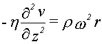
where z and r define a cylindrical coordinate system aligned with the axis of substrate rotation, v is the fluid velocity in the radial direction (a function of depth), and where 𝛒 is the fluid density, 𝛚 is the rotation rate in radians per second, and 𝛈 is the viscosity in poise. With appropriate flow and velocity boundary conditions, and considering a film that is initially uniform, the film thickness as a function of time, h(t), was found to be:
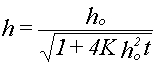
where ho is the film thickness at time zero (but not physically meaningful because of the first stage of unstable solution expulsion at early time), and K is a system constant defined as:

These equations are strictly valid only when K is constant. However, for spin coating of sol-gel or other complex solutions this may not hold true during all stages of spinning. Both viscosity and density are expected to increase as evaporation progresses, so caution must be used when applying these equations. In their analysis, EBP also showed that for early stages of fluid thinning (before evaporation becomes important), the thinning rate would be defined as:

At longer times, solvent evaporation becomes an important contribution. Meyerhofer was the first to estimate the effect of this on final coating thickness [J. Appl. Phys. 49 (1978) 3993-3997]. A quite reasonable approximation is that evaporation is a constant throughout spinning, as long as the rotation rate is held constant (see below). Therefore, he simply added a constant evaporation term to the equation above. So, the governing differential equation became:

where e is the evaporation rate [ml/s/cm2] (this is effectively the contribution to the interface velocity that is driven by the evaporation process alone). Instead of solving this equation explicitly, Meyerhofer assumed that early stages were entirely flow dominated, while later stages would be entirely evaporation dominated. He set the transition point at the condition where the evaporation rate and the viscous flow rate became equal. This can be thought of as the fluid-dynamical "set" point of the coating process. When these assumptions are made, the final coating thickness, hf, is predicted to be:

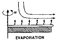
where co is the solids concentration in the solution. When the physically applicable dependence of the evaporation rate on spin-speed was factored in, this was successful in matching the regular exponents for the dependence of final film thickness with spin speed. Research has shown that the evaporation rate should be constant over the entire substrate and depend on rotation rate according to:

where the proportionality constant, C, must be determined for the specific experimental conditions. This square root dependence arises from the rate-limiting-step being diffusion through a vapor boundary layer above the spinning disk. It should be noted that this results when airflow above the spinning substrate is laminar.
Fluid Flow Complications: The flow behavior described above ignores several effects that are important for many coating solutions. As noted above, the evaporation step is critical in defining what the final coating thickness will be. But, evaporation occur -- by necessity -- from the top surface, and only some of the solution components are volatile enough to evaporate to any substantial degree. Thus, there will necessarily be an enrichment of the non-volatile components in the surface layer of the coating solution during the spinning process. The figure at right illustrates that concept. One of the key consequences is that this surface layer will very likely have a higher viscosity than the unmodified starting solution (this may simply be due to the higher concentration, but might also occur because of cross-linking effects, etc). With a higher viscosity, it will then impede the flow characteristics set out above, making it a difficult differential equation to solve directly. And, this surface layer may have the secondary result of reducing the evaporation rate. So both the evaporation and flow processes are coupled through the behavior of the "skin" that develops on the top of the outwardly flowing solution during spin coating.

Another important effect is that some solutions are not "Newtonian" in their viscosity/shear-rate relationships. Some solutions change viscosity depending on what shear rate is used, thus depending on distance from the center, the shear rate will be different and thus the flow behavior. This can give radial thickness variation that varies rather smoothly in a radial sense, as pointed out by Britten and Thomas [J. Appl. Phys. 71 (1992) 972-979].
Common Defects Found When Spin Coating
This is by no means an exhaustive list, but I try to highlight a number of defects/features that are characteristic of spin coated films.
Comets: These usually occur when relatively large solid particles impede the normal flow patterns of the solution on the spinning wafer. Except during "spin up", the flow is normally smooth and radial in nature (having a gradient in radial velocity governed by the applicable force balances and viscosity constraints The presence of comets can be reduced or eliminated by working in cleaner environments and by filtering coating solutions as part of the dispense process.
In the figures below the flow was from left to right and the scale is the same for all photos. All are light microscopy photos. So color differences indicate different coating thickness at different locations. These coating differences are most dramatic for the photo on the Bottom.

Sol-gel PZT on Silicon wafer

Sol-gel PLZT 2/50/50 on conductive-oxide-coated glass. 2000 RPM spinning speed. Tiny BaTiO3 seeding particles in suspension. (more visible in close-up).

Sol-Gel Silica-titania on silicon. 1000 RPM spinning speed. Nominal coating thickness = 300 nm.
Striations: Striations are radially oriented lines of thickness variation in the as-coated film. Usually they are quite smoothly varying thickness variations with a spacing or periodicity in the 50-200 micron range, or so. Their orientation corresponds the direction of major fluid flow (which is running horizontally in 2 of the 3 the optical micrographs shown below). Their occurrence is thought to arise because of evaporation driven surface tension effects. The early evaporation of light solvents can cause an enrichment of water and/or other less volatile species in the surface layer. If, the surface tension of this layer is larger than the starting solution (and what still exists at deeper levels), then an instability exists where the higher surface tension actually draws material in at regular intervals and the spaces in-between are more able to evaporate, and surface relief develops. This is essentially due to the Marangoni effect which governs the development of structures in the drainage patterns of wine down the sides of a wine glass: ethanol evaporates first leaving an ethanol-depleted wine layer that gathers into rivulets and drains down the glass wall.

Sol-Gel Silica-titania. 1000 RPM - nominal thickness=300 nm.

Sol-Gel PZT viewed near edge. 3000 RPM - average thickness not resolved in ellipsometry

Sol-Gel PZT viewed at center. Same sample as figure to left. Radial flow of fluid stretches out the cellular features shown above.
Evaporation driven surface tension effects can create striations the following way:

The evaporation process makes the top layer have a different composition and therefore a different surface tension. The top surface then can become unstable to "long wavelength" perturbations that grow unstably. The exact conditions that control what is stable and what is unstable are still not well known. Our preliminary model is that you would like the evaporation process to be driving the local surface tension to lower values and that this would tend to stabilize the system. This is currently being tested on a number of sol-gel and polymer coating systems.
Chuck Marks: These patterns can be created by thermal "communication" between the solution on top of the wafer and the metal vacuum chuck on the back side of the wafer . Thus, the thermal conductivity of the substrate material is very important as is the thermal driving force (mainly evaporative cooling, but could also be due to temperature differences between solution and substrate and chuck). The figure at right has a single layer sol-gel-derived coating on a glass substrate.Silicon wafers, because of their higher thermal conductivity, will usually have smaller thickness differences compared to glass or plastic.

Environmental Sensitivity: When making coatings in the ambient environment, it is possible for the surroundings to have an influence on the coating quality. One critical variable is the humidity of the surrounding air. For many solutions, water can play an important role in the chemistry of the solution itself, so when varying amounts of water are present in the surroundings then varying coating quality can result. This can manifest itself as coating roughness, microcracking of the coating upon further drying, exaggerated striation formation in the coating, etc. Obviously, close control of the environment around the spin coater is crucial.
Wafer Edge Effects: The edges of the substrate will always be areas of concern. If better uniformity can be maintained out to the edges then more area can be used for device fabrication. The edges are problems for several reasons. First, surface tension effects make it difficult for solution that is flowing radially outward to detach from the wafer. Thus a small "bead" of liquid can stay attached around the entire perimeter and result in thicker coatings in this rim zone. In addition, if substrates are not exactly round and especially if they are square or rectangular, then the airflow over the protruding parts (corners) will be perturbed. Although the flow may still be laminar, it will have different flow history and will usually result in non-uniformity in coating thickness in these corner areas.
Just ask!
Please fill up the form to help us serve you better